
‹


›
1、 Overview:
The dynamic stiffness testing system for isolators is mainly used for testing the dynamic stiffness and durability fatigue of isolators, shock absorbers, and elastic components;
The system is mainly composed of a closed-loop servo control system consisting of an electrical controller, servo valve, load sensor, displacement sensor, and computer. It can automatically and accurately control the test process and automatically measure test parameters such as force, displacement, deformation, torque, angle, etc.
The testing machine can achieve waveforms such as sine wave, triangular wave, square wave, sawtooth wave, anti sawtooth wave, pulse wave, etc. It can perform mechanical tests such as tension, compression, bending, low cycle and high cycle fatigue. Environmental testing equipment can also be configured to complete environmental simulation tests at different temperatures.
The testing machine is flexible and convenient to operate, and the lifting, locking, and specimen clamping of the moving crossbeam are all completed by button operation. It adopts advanced hydraulic servo drive technology for loading, high-precision dynamic load sensors, and high-resolution magnetostrictive displacement sensors to measure the force and displacement of the specimen. The fully digital measurement and control system realizes PID control of force, deformation, and displacement, and each control can be smoothly converted between them., The experimental software works in the WINDOWS XP/Win7 Chinese environment, with powerful data processing capabilities. The experimental conditions and results are automatically saved, displayed, and printed. The entire experimental process is controlled by computers, and the testing machine is an ideal cost-effective testing system for industries such as research institutes, metallurgical construction, national defense and military industry, colleges and universities, mechanical manufacturing, transportation, etc.
In response to the actual needs of this project, this plan adopts three sets of host framework units, one set of comprehensive power unit (hydraulic station), and three sets of independent control systems for laboratory construction; Three independent measurement and control systems are matched with three independent load frames, which do not affect each other and can simultaneously meet different testing requirements;
2、Relevant standards:
1) GB/T 2611-2007 General Technical Requirements for Testing Machines
2) GB/T16825.1-2008 "Inspection of static uniaxial testing machines - Part 1: Inspection and calibration of force measuring systems for tensile and/or compressive testing machines"
3) GB/T 16826-2008 "Electro hydraulic Servo Universal Testing Machine"
4) JB/T 8612-1997 "Electro hydraulic Servo Universal Testing Machine"
5) JB9397-2002 Technical Conditions for Tensile and Compressive Fatigue Testing Machine
6) GB/T 3075-2008 "Metallic Axial Fatigue Test Method"
7) GB/T15248-2008 "Axial constant amplitude low cycle fatigue test method for metallic materials"
8) HG/T 2067-1991 Technical Conditions for Rubber Fatigue Testing Machine
The main components of this experimental equipment:
1、High stiffness four column load frame; 3 sets
2. Intelligent constant voltage silent power source; 1 set
3. Fully digital dynamic and static control system; 3 sets
4. Chinese English human-machine dialogue lower computer operation application software (dynamic and static stiffness testing package); 3 sets
5. Advantech Industrial Computers and Machine Printers; 3 sets
6. Conventional auxiliary equipment related to experiments;3 sets
.png")
.png")
Overall layout diagram
3、Main technical indicators and configurations
3.1 Technical Parameters and Specifications
3.2 Configuration Details
4、Main Unit Introduction:
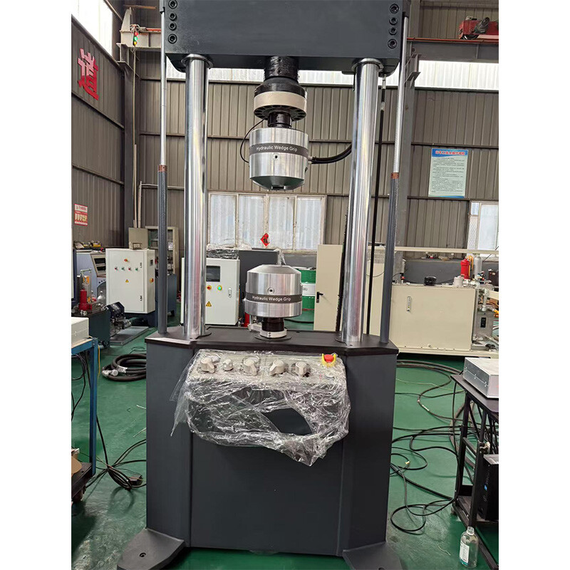
1. Host loading framework
(As shown in the following diagram)。

l Our high-frequency and high stiffness seamless load-bearing frame products;
l Four column host frame, with hard chrome plated and polished columns, effective distance between columns: 550mm; The diameter of the column is 100mm.
l Upper crossbeam: hydraulic lifting, hydraulic locking. Maximum adjustable test net space: 1000mm.
l Workbench height: 350mm.
l Rack stiffness: 3 × 10⁸ N/m
2、Static pressure support servo actuator
l Dynamic test load: ± 75KN
l Static test load: ± 100KN;
l Maximum travel: ± 75mm (total travel 150mm);
l Suitable for dedicated high-speed servo actuators with high cycle and high frequency;
l The static pressure support actuator is a high-end servo hydraulic cylinder manufactured based on the principle of liquid static pressure support technology. It has a series of advantages: pure liquid friction, low friction coefficient, no direct contact between metals, low wear, resistance to lateral forces, long-term maintenance of high precision, large speed range, can be used for both high and low speeds, high control accuracy, etc. Widely used in various fields such as fatigue testing, vibration swing tables, dynamic testing of aircraft and automotive parts, etc,
l In hydraulic servo control, due to the high precision requirements for position, speed, or force control, traditional sealing and support methods are used. Regardless of whether the piston rod extends or rotates, the piston rod inevitably rubs against the cylinder or end cap. The higher the frequency of movement, the more obvious the friction, resulting in defects such as wear, oil leakage, heat generation, high starting friction, low frequency response, and high heat generation; If the piston rod still experiences lateral force during movement, it will further amplify the above-mentioned defects. The traditional sealing form can no longer meet the control requirements of high precision, high load, and high frequency response.
l After adopting the static pressure support technology, a high-pressure oil film is established in the extremely small gap between the piston rod, cylinder barrel, and end cap, allowing the piston rod to move in a suspended state, with pure liquid friction and no direct contact between metals, which can maintain low friction for a long time. Combined with the high-precision machining accuracy of the piston rod surface, the control accuracy and service life of the static pressure cylinder are greatly improved. Under the feedback adjustment of the high-pressure oil film, it can also resist considerable lateral loads, so that even with lateral forces, extremely low friction resistance and ultra-high service life can still be maintained.
l Sensor:
Ø Force sensor: a product of Interface Corporation in the United States, used for tension compression bidirectional fatigue and sensing. The maximum test force is ± 125kN, with an overload capacity of 150%. When combined with the control system, the indication error is ± 1%; Before leaving the factory, the sensor calibration is completed;
Ø Displacement sensor: a product of a sophisticated American company, LVDT displacement sensor, with an effective range (maximum displacement) of ± 150mm, coordinated with the control system, and an indication error of ± 0.5% FS; Before leaving the factory, the sensor calibration is completed.
l Servo valve: MOOG servo valve from the United States, single valve flow rate of 63L/min, pressure of 21Mpa, dual valve total flow rate of 120L/min; Directly integrate the servo valve mounting seat with the actuator; (Dual valves can be used in parallel if necessary)
.jpg")
.jpg")
.jpg")
3、Constant voltage servo power source
The constant pressure servo pump station is generally installed centrally in the planned pump room. The piping system directs hydraulic oil to the vicinity of the main engine, and then connects the servo actuator through a hose circuit oil separator hose circuit.
The pump station is a standardized pump station with modular design, which theoretically can be cascaded into large-scale pump stations of any flow rate, thus having good scalability and flexible use.
l The total flow rate is 100L/min and the pressure is 21Mpa. (Adjust according to experimental requirements)
l This site adopts dual motor pump sets, with a single pump set of 50L flow rate, and can only choose the number to be turned on, which is more energy-efficient and efficient!
l Total power 44kW (22KW × 2), 380V, three-phase, 50Hz, AC。
l The pump station is designed and manufactured according to standard modular design, with mature technology and stable performance; Configure the relay voltage stabilization module and connect it to the actuator.
l The pump station is composed of oil pump, motor, high and low pressure switching valve group, accumulator, oil filter, oil tank, pipeline system and other parts;
l The filtration system adopts three-stage filtration: oil pump suction port, 100 μ; Oil source outlet, filtration accuracy of 3 μ; Relay voltage stabilization module with a filtering accuracy of 3 μ.
l The oil pump adopts the German Defu internal gear pump, which adopts involute internal gear meshing transmission, low noise, excellent durability and long service life;
l The oil pump motor unit is equipped with a damping device (using damping pads) to reduce vibration and noise;
l Use high and low pressure switching valve groups to start and stop the hydraulic system.
l Fully enclosed standard servo fuel tank, with a tank capacity of not less than 300L; It has functions such as temperature measurement, air filtration, and oil level display;

4、Experimental fixtures and jigs
l Design according to the characteristics of the sample and the testing method.
l Other accessories and sensors are designed to complement each other.
4.4 Provide attached interface drawings;
5、Pipe system:
l All hydraulic soft pipelines are made of PARKER products from the United States.
l The length of the pipeline between the host and the pump station is 3-6m (determined according to the layout of the laboratory);
l Other hose routes include: hydraulic clamp hose route, lifting cylinder hose route, and a complete set of imported hoses from the United States.
6、Electrical control system
● Cabinet structure, placed near the pump station body, Siemens PLC intelligent remote control.
● Design to meet the national standards for strong electrical system design;
● Automatically switch between high and low pressure in the pump station, start at low pressure, and run at high pressure;
● Total power: 37kW, AC,380V, Three phase five wire system.
● The cabinet is equipped with voltage and current meters, and is equipped with relevant buttons to control the start and stop of two sets of motors.
● Equipped with multiple protection and alarm functions such as low liquid level, temperature exceeding limit, oil filter blockage, motor overload, etc;
● Reasonable layout of wires and cables, easy maintenance and use, and beautiful appearance;
● The first party is responsible for the power supply.
● Remote control cabinet
Ø Placed in the control room, the PLC control room controls the start and stop of three sets of motors;
Ø The alarm operation indicator light is clear and reliable;
Ø Equipped with a remote electronic pressure gauge to monitor the pressure of the pump station, and equipped with multiple alarm indication functions such as oil filter blockage and temperature exceeding.
Ø Using a safe 24V working voltage, safe to use, aesthetically pleasing in appearance, and easy to operate
7、Cooling system (water-cooled machine)
8、Control system and computer software system
8.1 Main configuration components of the controller:
l Test force signal conditioning unit, 3 sets;
l Displacement signal conditioning unit, 3 sets;
l Signal generator unit, 3 sets;
l Full digital closed-loop control, allowing for arbitrary signal acquisition for full digital PID control. Closed loop control frequency up to 6kHz;
l Control waveforms: sine wave, triangular wave, square wave, oblique wave, sawtooth wave, random wave, free wave, and can achieve combined output of various waveforms.
l Control method: PID closed-loop control of force, displacement, and deformation, and can achieve smooth and disturbance free switching of any control mode;
l The system has functions such as sensor calibration and reset;
l Realize high-speed data communication with computers through Ethernet cards;
l Provide multiple interface boards to match various sensors and drive units.
8.2 Software system.
The software system is a mainstream multi-channel dynamic testing system, which is particularly suitable for various scientific research institutions due to its wide range of test standards, flexible use, and convenient and fast data import and export. The main functional features include:
l Developed based on the Win7/10 working platform;
l Integrate various dynamic testing functions into one.
l For dynamic testing, any combination of test waveforms can be defined to form a test spectrum and process, and the testing machine can be controlled to complete various complex functional dynamic fatigue tests.
l For static testing, the software integration material testing field mainly includes international standards and domestic GB standard software modules, which have powerful functions and are suitable for both scientific research and conventional process research.
l Various functions such as data collection, testing steps, data storage, and testing protection can be programmed in the form of events to assist users in completing complex testing operations.
.png")
.png")
.png")
.png")
.png")
8.3 Computers, printers
l Taiwan Advantech brand industrial computer
l 24 "LCED monitor.
l Win7 operating system.
l HP A4 laser printer.
9、Experimental attachments
l Specialized auxiliary equipment for vibration isolators;
l Provide drawings of experimental aids;
10、Spare parts and tools:
l Spare filter element (filtration accuracy 3 µ): 1 piece, used to replace the filter element when the oil filter is clogged;
l Flushing module solenoid valve: 1 piece;
l Equipment specific tools, 1 set
MESSAGE
MESSAGE
RECOMMEND PRODUCTS
RECOMMEND PRODUCTS
Get real-time quotes
Interested? Leave your contact details.